
TECNA · Electric bus and truck depots
Overhead cable management for HPC depots
TECNA Overhead Cable Management keeps the CCS charging cable suspended. The operator lowers the connector to plug it in. After charging, the system raises the cable at a controlled speed to clear the bay.
- Connector and current
- CCS up to 500 A
- Charging cable length
- Up to 9.5 m
- Environment
- Indoor and outdoor
From plugging in to overhead storage
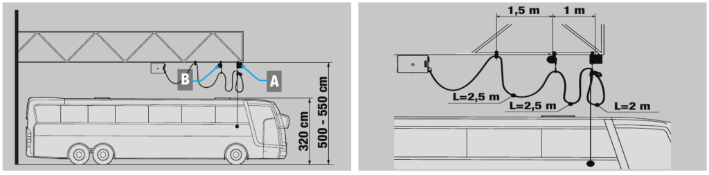
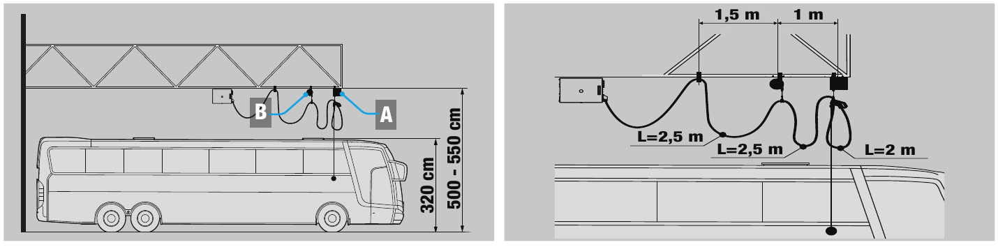
Two balancers support the cable between the charger outlet and the vehicle. The bay layout determines the positions of the balancers and the connector’s reach.
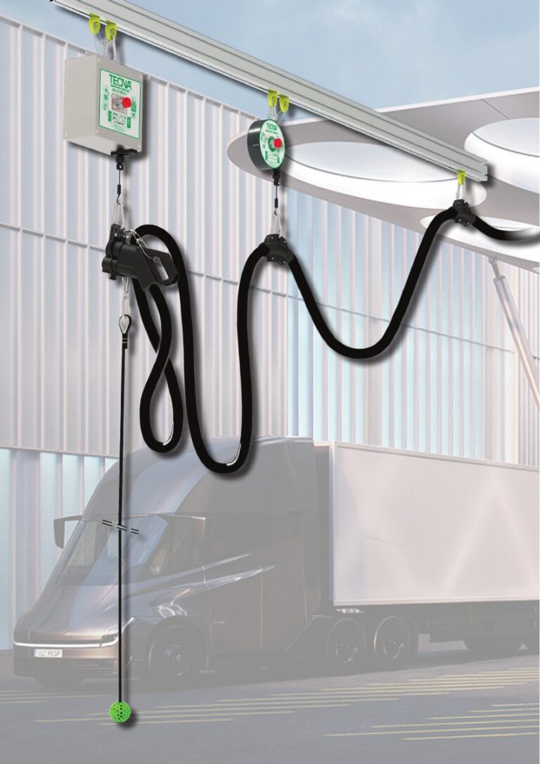
Lower the connector
The operator uses the pulling rope to bring the connector within reach and plug it into the vehicle.
Support the cable
The main 9702OD balancer supports the connector end as it moves. The auxiliary balancer supports another section of the cable.
Raise it after charging
After unplugging, progressive braking in the 9702OD controls the speed of retraction to the resting position.
Two kits for different CCS cables
TECNA specifies which cable currents each kit supports. GEDO also considers the weight of the cable and connector, the required reach and the suspension points to confirm the configuration.
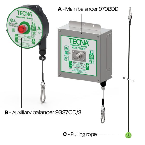
TECNA IB01320003
Kit MEDIUM
- CCS cable current
- Up to 380 A
- Auxiliary balancer
- 9337OD/3
- Auxiliary working travel
- 3 m
- Auxiliary progressive pull force
- 4–6 kg
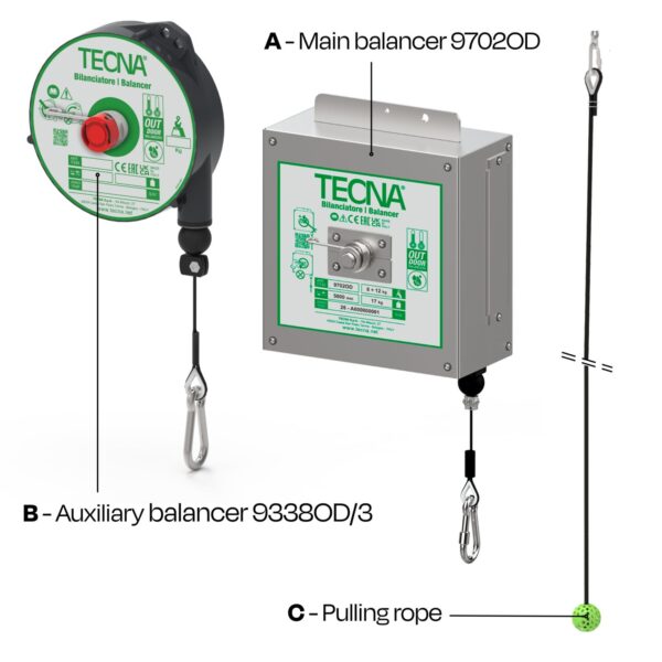
TECNA IB01320004
Kit HEAVY
- CCS cable current
- 400 A or 500 A
- Auxiliary balancer
- 9338OD/3
- Auxiliary working travel
- 3 m
- Auxiliary progressive pull force
- 6–8 kg
Both kits include the 9702OD main balancer, the listed auxiliary balancer and a pulling rope. The 9702OD has a 5 m working travel and a pull-to-lock feature.
TECNA specifies a progressive pull force of 8–12 kg for the 9702OD. The pull setting is adjustable on both balancers, and the ranges apply to each unit individually.
TECNA specifies a charging cable length of up to 9.5 m and a balancer operating temperature range of −40 °C to +60 °C.
Prepare your project and quote
For a new depot or an existing charger, send the bay plan and the cable datasheet. The quote specifies the selected kit and what is included.
- Charger and cableCharger make and model, cable reference, connector, current, length and weight including the connector.
- Bay layoutMounting height and location, charger and vehicle inlet positions, required reach and desired storage height.
- Exposure and quantityIndoor, sheltered or exposed installation, number of charging points and any differing layouts.
Example gantry layout
Can the kit be fitted to an existing charger?
The assessment starts with the existing cable and the bay plan. Vehicle positions, available clearance and suspension points determine feasibility.
How should I plan for mounting and installation?
Specify whether a rail, gantry or other supporting structure is in place. The quote can then specify the fixings and installation work required.